Reviving a FlashForge Creator Pro
How I improved an old 3d printer and gave it a second life
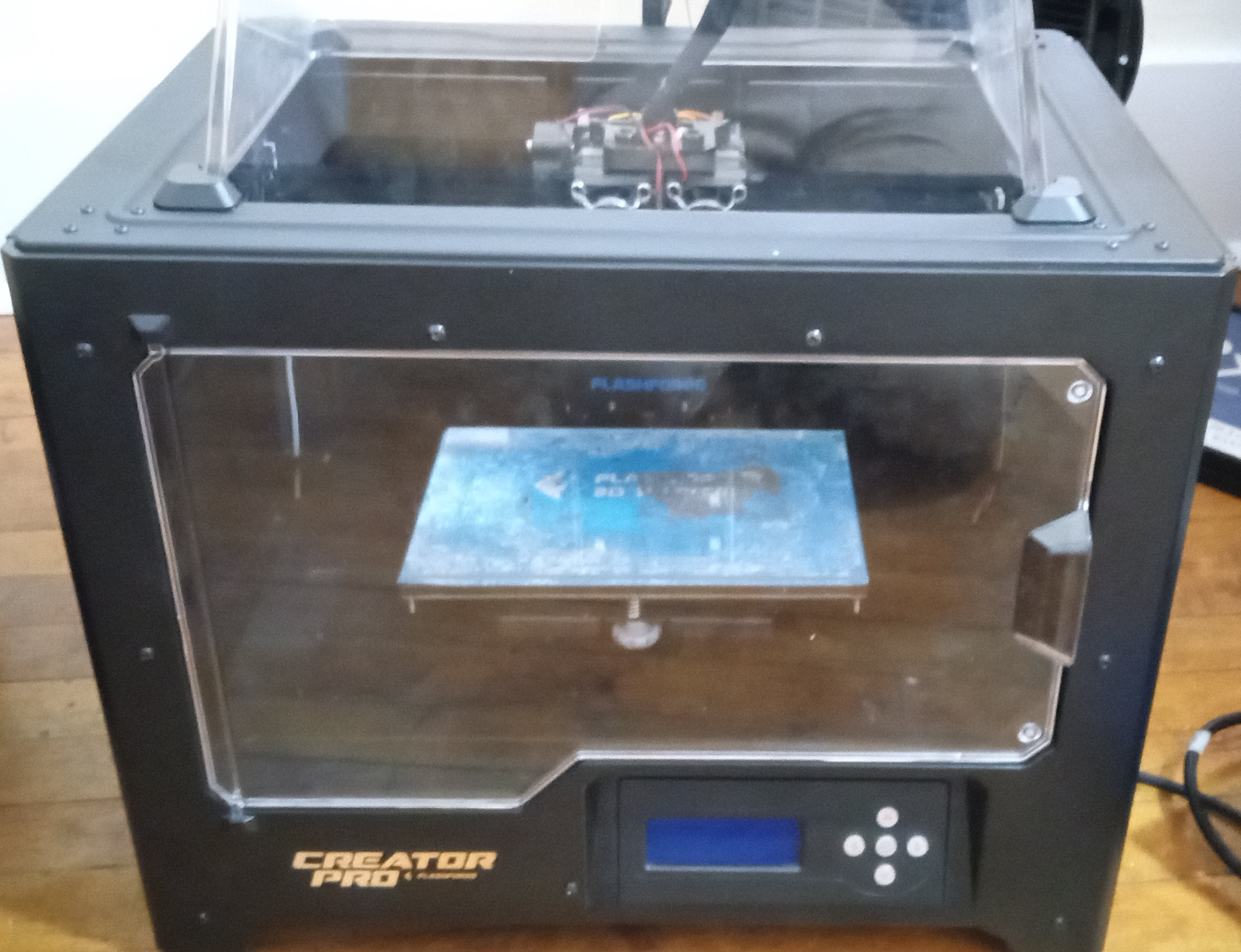
I recently received an old FlashForge Creator Pro that was no longer in commission. The possibilities were apparent, but there was work to be done to modernize and improve it. Here I'm going to go through some of the mods I've made and how I went about making them. The machine itself has a lot of things going for it: it is well constructed, can come with dual extruders (which are admittedly a bit of a gimmick), has a reasonably sized print area, has a partial enclosure so it can print ABS and other temperature sensitive materials, and has the potential for good quality prints. It also has some issues though, for example I couldn't get it to work while tethered with Flashprint or any other slicers/hosts I tried, which limits usage to copying GCode onto an SD card. It doesn't have automated bed leveling, and the stock bed on my particular printer was well worn. It also doesn't have filament runout detection, so you've got to keep a closer eye on it if you're low on filament. The primary modifications I've made so far are: switching from the original Sailfish firmware to Klipper and Mainsail to provide a web based printing interface, installing a BL Touch sensor to enable automatic bed leveling, installing filament runout sensors to pause long prints if filament runs out, and switching to a glass bed.
Warning: I am a hobbyist not an expert, and I would like no responsibility for any potential damage or problems that might result from trying the steps I detail here. Ideally you should have experience dealing with electronics and firmware before performing any of these steps, to get you through any snags. Updating the firmware on your printer is going to be destructive, and some of the hardware modifications may have the potential to damage components if done incorrectly, so make sure that you're certain that you want to do this before you get started. While the work you do in these modifications isn't particularly dangerous with the right precautions, you will be taking apart a piece of electrical equipment that has heating elements and a power board that converts grid power to safer voltages, and there are always risks associated with this. Please take precautions to mitigate risks of fire, electrocution and other possible tragedies.
- Getting at the control System
- Switching to Klipper and Mainsail
- Installing a BL Touch
- Installing a Filament Sensor
- Installing a Glass Bed
- Resources
Getting at the control system of the Creator Pro
Prerequisites
- A Philips head screw driver
- An Allen key set with a 3/32" or 2.5mm key
- A FlashForge Creator Pro printer
A lot of the steps ahead are going to require you to take apart your printer, so I'm going to start with a quick run through of how to do that, and then assume that you can do it when necessary in the sections ahead. Make sure that you're printer is unplugged and powered off, if you don't do this you may be at risk of electrocuting yourself or damaging components. Reassembly is the same process but in reverse. You'll want to make sure when reassembling that you don't forget to plug the LCD cable back in, as it is easy to forget, and the vent is a bit trickier to put back in than it is to take out.
Removing The Door Panel
I found that the easiest way to take apart the printer was to start by removing the top enclosure cover and flipping the printer upside down with the door facing you. From here there are 9 Allen head bolts to remove as shown (the printer isn't upside down in the photo, but you'll want it to be since the controls are on the bottom).
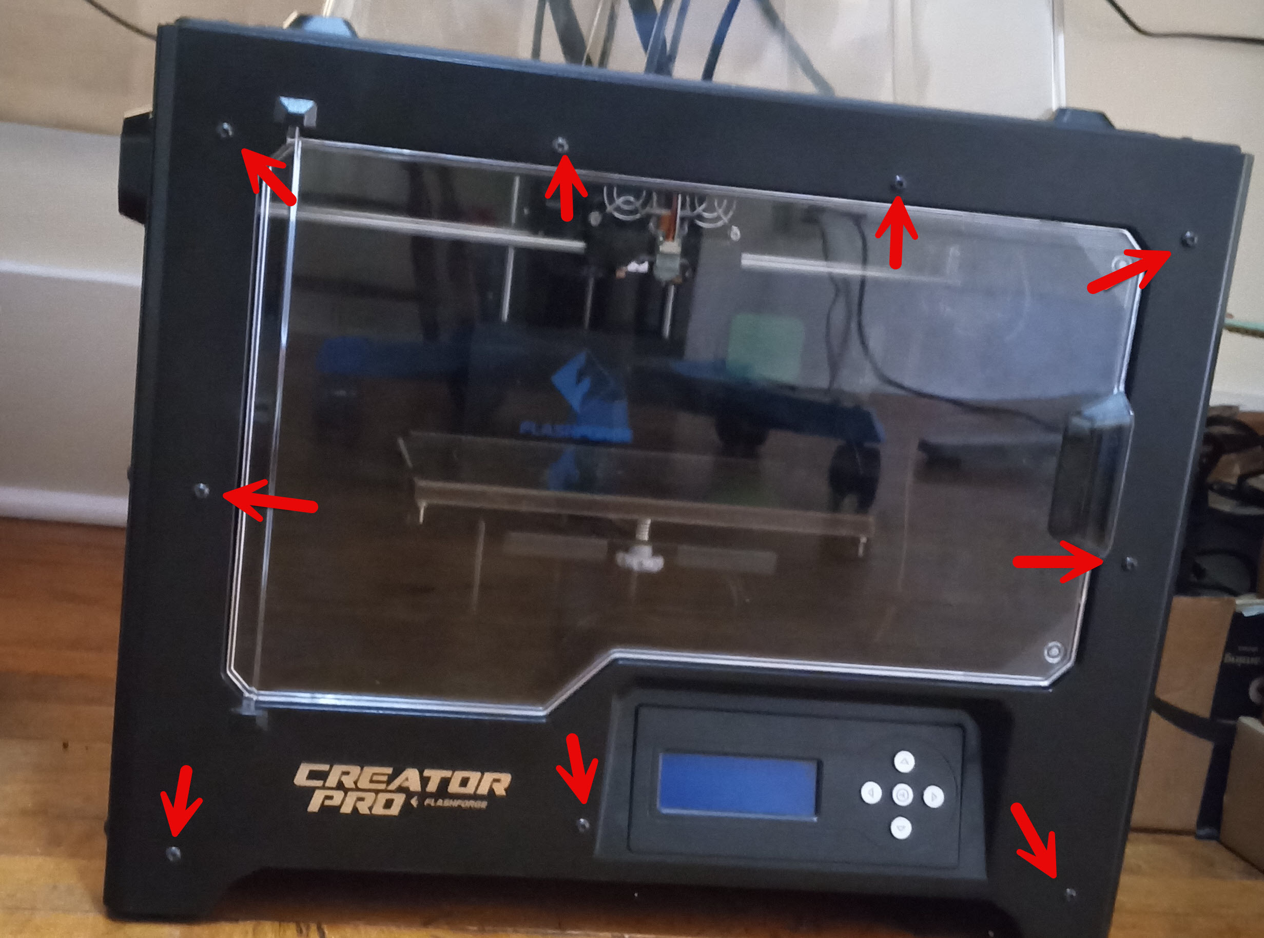
Once you've removed these bolts, there are two more on the bottom vent (now the top if the printer is upside down) that connect the vent to the door panel, which will also need to be removed.
After this, you can carefully pull the panel away, but you won't be able to remove it fully without detaching the LCD display cable, which will require fully removing the bottom vent.
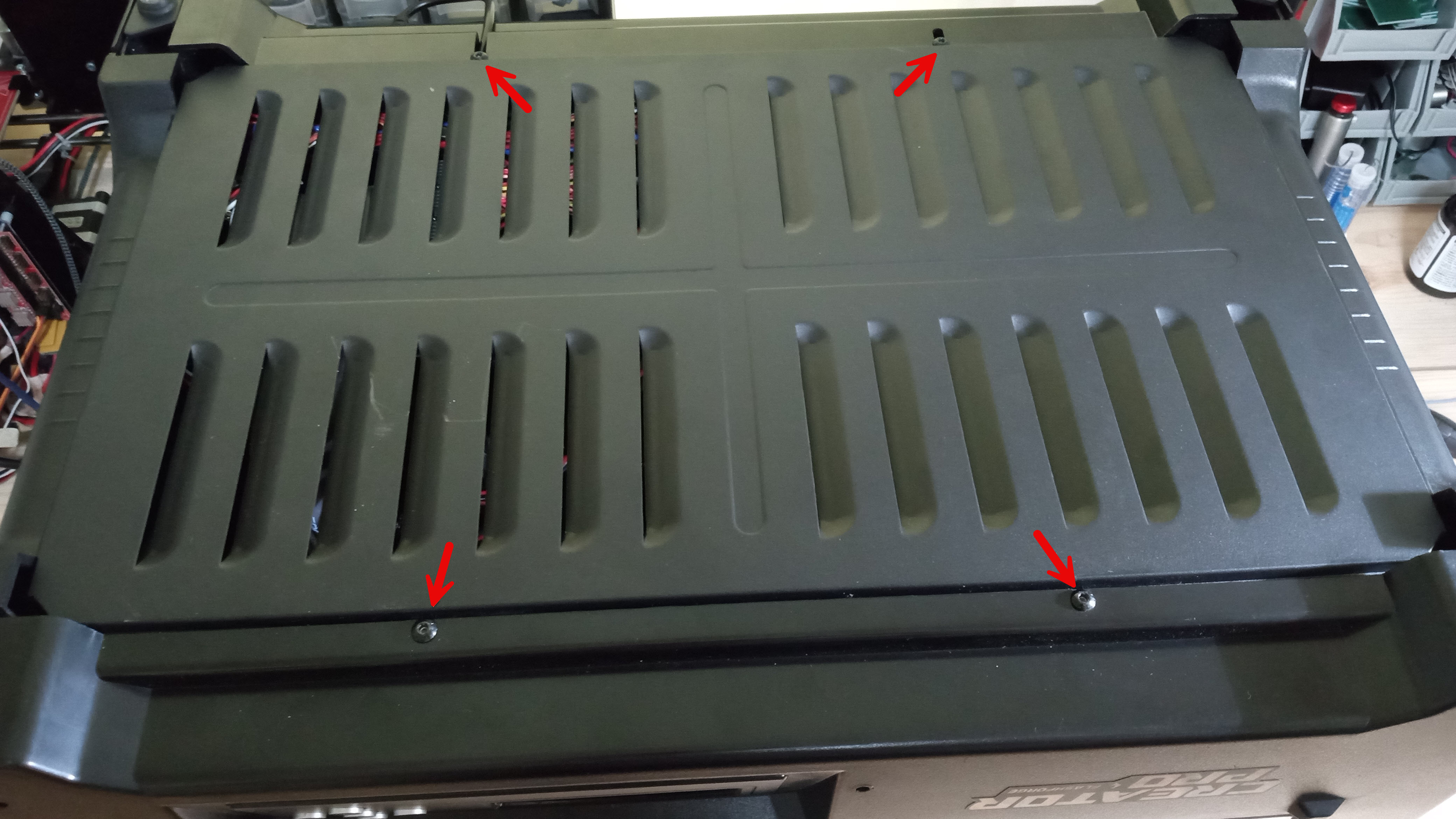
Removing The Bottom Vent
The bottom vent has 4 Allen head bolts as seen in the picture above. The vent will only come off if you remove these bolts and remove one of the panels to allow room for it to slide out, otherwise it will become loose, but it won't be actually be able to fit when trying to remove.
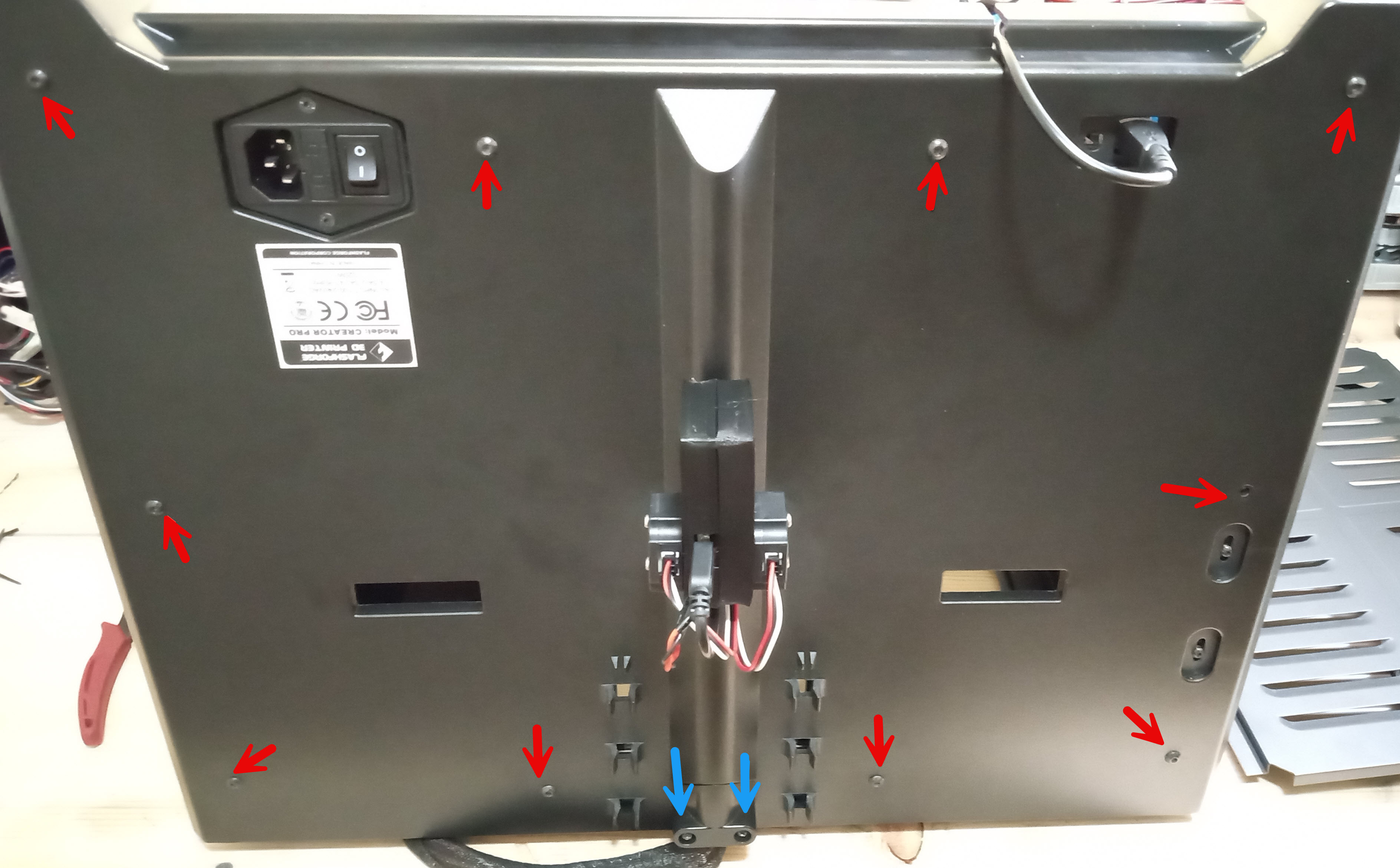
Removing The Back Panel (helpful for eventual cable management and routing)
The back panel has 10 Allen head bolts to remove, as shown in red. Make sure to only remove the ones shown below as a few of the bolts are used to mount the z axis stepper motors. The two screws indicated in blue are Philips head screws that are used to affix the cable harness for the printer, if you remove them it will help with cable management.
Switching to Klipper firmware and Mainsail
Prerequisites
- $15 - A Raspberry pi or other supported Single Board Computer (see MainSail's supported hardware). I used a Raspberry Pi Zero 2 W, which worked well. This will be what runs MainSailOS and the web printer interface.
- $10 - A USB Type B to Micro USB cable, or another USB type B cable that can be used to provide communication from your printer to your SBC. In the case of the PI Zero 2, the only inputs available are Micro USB, so you'll need this special USB type B to Micro USB for it. This is only for serial communication, the Creator Pro does not provide power via its USB Type B port.
- $10 - A Micro SD card for storage of MainSailOS, ideally you'll want an A1 class card to ensure the read and write speeds will allow MainSail to run with good performance. I'd recommend having a card above 16 GB, so that you'll have some space for prints to be stored (mine is 64GB).
- $10 - A Micro SD card reader, needed to flash the micro SD card with firmware and operating system.
- (Optional) $15 - A micro HDMI cable and micro USB keyboard or micro USB hub to allow display and control of the Pi Zero during setup. If you're comfortable setting up the PI Zero in headless mode this isn't needed, but can be helpful for debugging.
- (Optional) A buck converter, such as eBoot Mini MP1584EN that is capable of converting 24v to 5v DC-DC power, to provide power to the Raspberry Pi.
- (Optional) A 100 Ω resistor to use as a dummy load for calibrating the buck converter.
- (Optional) Some 22 gauge or thicker wire to provide your own power to the Raspberry Pi. Ideally with some ring connectors and shrink tube, or at least some electrical tape to insulate any exposed wire and prevent shorts.
What is Klipper?
Klipper is 3d printer firmware, like the original Sailfish firmware on the Creator Pro. Klipper does something a bit unique though. Instead of having the microcontroller do everything, it utilizes a computer such as a Raspberry Pi to do the bulk of the processing, and then uses some lightweight firmware on the microcontroller to focus on handling the IO of controlling the printer. This approach enables more advanced features and functionality, and the seperation also means that you potentially have options for the interface you use to talk to Klipper (I'm using Mainsail, but you could also use Octoprint or Fluidd). With Klipper you setup a simple configuration file to tell the firmware how your printer is laid out, and then you install a lightweight image that gets flashed to the actual micro controller (for the creator pro, an ATMega2560 which is the basis for the MightyBoard it uses). With these two things working in unison, you get a fairly easy installation process with significant improvements on the overall performance of the printer, specifically when compared to other alternatives such as Marlin paired with OctoPrint.
What is Mainsail?
MainSail, similar to Octoprint, is a prebuilt image for single board computers (SBCs), which will provide us with a clean and easy to use web interface for interacting with our printer. It also is paired with Klipper to allow for easy configuration and setup of the printing firmware on the ATMega2560. MainSail will give you the interface for uploading your GCode files and printing them, as well as other features. Sitting in between Klipper and Mainsail is a robust API called Moonraker, which is how Mainsail talks to the Klippy host and Klipper firmware on the MightyBoard.
Installing MainsailOS
The setup for MainSail OS is not too difficult (if you don't run into weird issues like I did, otherwise it has the potential to be a pain*). You can find up to date instructions on Mainsail's website, but here's a quick summary of the steps:
- Make sure your SD card is inserted into your card reader and connected on your computer.
- Install the Raspberry Pi Imaging Tool, which is what you'll use to write the MainSail image onto the SD Card.
- Choose your device type (in my case, the Pi Zero 2 W), and for the Operating system you'll want to navigate to "Other specific purpose" OS, then "3D printing" and finally choose "Mainsail OS" and select the OS type that makes the most sense (in some cases there may only be one).
- Select the SD card as the storage device to write to.
- Customize your settings more when prompted, including setting up your WiFi credentials, and making sure that SSH is enabled, so that you'll be able to login to the device later for additional configuration.
- Once you have all the settings you want, you can write the MainsailOS to the device. After it finishes writing and validating a successful image you can eject your card and put it into your SBC. If you have a power source for the raspberry pi, such as a micro USB cable, you can try powering it up now and continue to the next section to configure Mainsail. Otherwise you can continue on to the steps for powering it with your printer's power supply.
- If you've installed successfully, you should be able to access your Mainsail installation by navigating to http://mainsailos.local/ (if you set a different hostname during setup it will be a different URL than mainsailos) or if that isn't working use the IP address of the device assigned by your router.
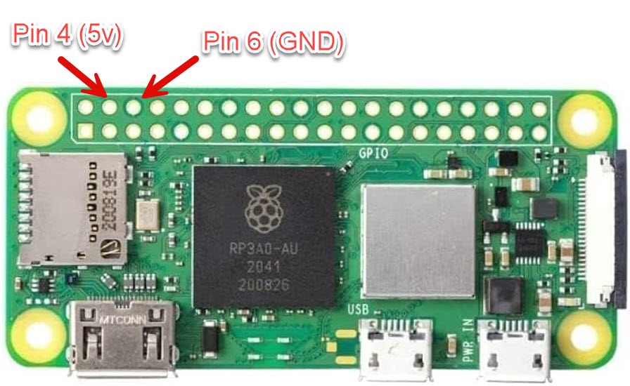
*Note: I ran into a number of issues during my installation of Mainsail. The first was that the Raspberry PI imaging tool kept being unable to write the image to the SD card, this turned out to be due to the card reader I used not being very reliable, but can also be due to poor quality SD cards as well, so if you run into that issue try a different card or reader. After that, when I went to verify that the mainsail OS was actually working I couldn't get the pi zero to show up on my network. This turned out to be because of poor power in the USB port I used, which was providing enough power to turn on leds but not enough to fully power up. You can check the voltage the raspberry pi is receiving with a volt meter across pins 4 and 6 (5v and GND), find a Pi pinout for reference or see the image in the next section. If your power source is below 5v and you don't see your pi showing up on your network, this may be your problem as well.
Powering Using Your 3D printer
This step can be skipped if you have another way you'd like to power your Raspberry Pi, such as with a normal micro USB cable, but in my case I wanted to piggyback on the printer's power supply as a power source so that I could run everything with one power cable. It is worth saying that the USB type B connection on the printer is not capable of supplying power for the Raspberry Pi. It will either need its own USB power adapter or some other power source. The steps I followed are loosely based on this video by Build it Make It, so that may be a helpful reference. Be sure that your printer is disconnected from power before continuing, as modifying a live power supply is a recipe for problems.
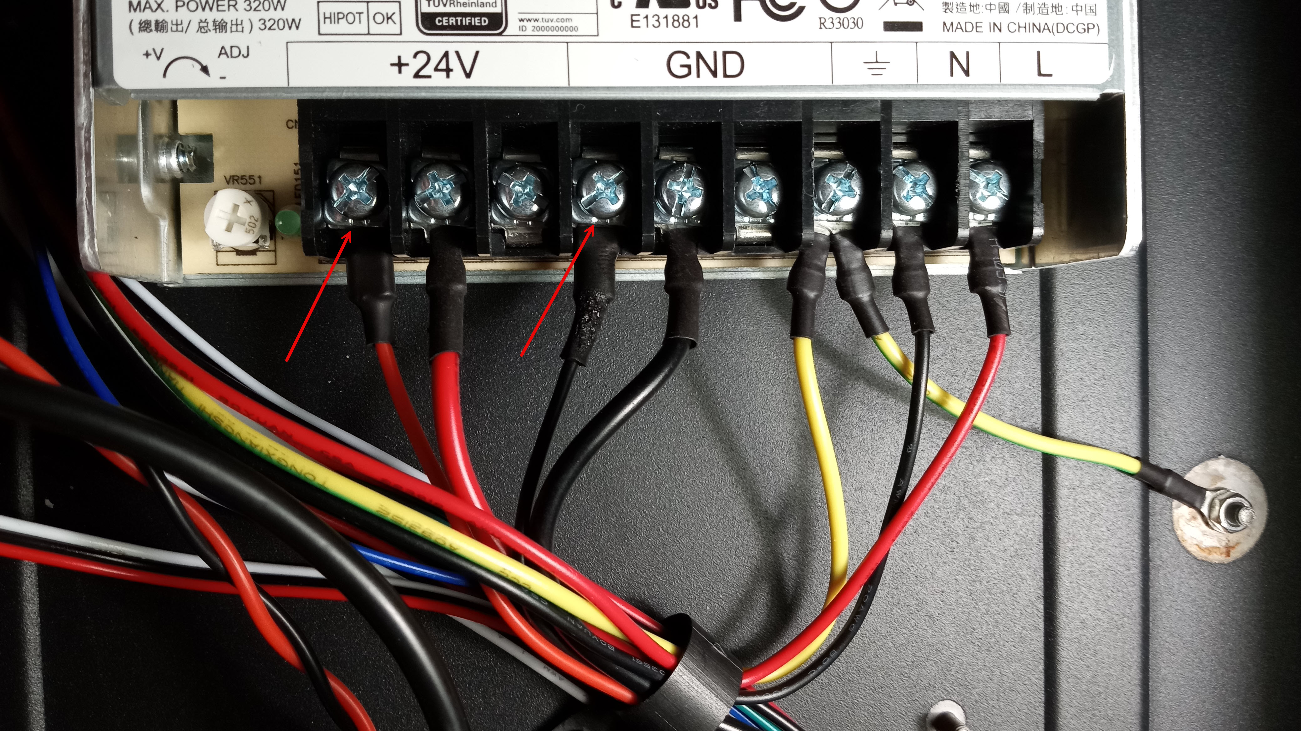
The first step to powering the printer is cutting a length of cable that will run from the power supply to the buck converter. This length can be relatively short, as you'll want to position the buck converter somewhere in the printer internals (mine is zip tied in place with some of the other cables). In my case, I stripped the ends of one red and one black wire, and crimped on ring connectors. I put some heat shrink tube on the connectors, because they were not insulated. I then screwed the red wire onto an open 24v power connector on the power supply, and the black onto one of the open GND connectors, as pictured.
Next the buck converter needs to be calibrated to make sure that the output on it is going to actually be 5v for the Raspberry Pi. To do this, you will need to connect the wires from the 24V power connectors to the "IN+" and "IN-" inputs of the buck converter. You'll want to solder them on so you have a solid connection. Now connect a 100 Ω resistor to the "OUT+" and "OUT-" outputs to act as a temporary dummy load (so that the voltage stays stable while you tune it). Turn on your power supply and check the voltage between the "OUT+" and "OUT-" side. While monitoring the output voltage, use a small screw driver to adjust the screw head on the buck converter until your volt meter reads 5v (alligator clamps, or a second pair of hands makes this easier). Note while you do this that the screw should hopefully be pretty stiff--if it is loose you might run into issues while printing since the printer may vibrate enough to adjust this setting overtime with a loose set screw, which could potentially cause power failures for the Raspberry Pi.
You should now have a buck converter wired up to provide a 5v power source that you can use for your Raspberry Pi. Cut a longer length of cable for the output side of the buck converter that will run to your Raspberry Pi. In my case I routed the cable through the loom and then out the back of the printer, so I measured the length along the cable loom to try and get a good guess at the length. With this cable cut, I crimped the wires into a female wire-to-board connector, and then soldered on a male wire-to-board connector on the raspberry pi itself, but you can also simply solder it on to the pi if you don't think you'll ever be disconnecting it. The cable should be wired to the pi so that the "OUT+" is connected to the pi pin 4, and OUT- is connected to pi pin 6. With the Pi wired up, you can try powering it on and verify that the voltage is set high enough. There may be scenarios where 5v isn't quite enough, which means you might need to repeat the process of increasing the voltage a little bit to ensure you have a properly powered Raspberry Pi (disconnect the Pi first, you don't want to accidentally fry it while making adjustments).
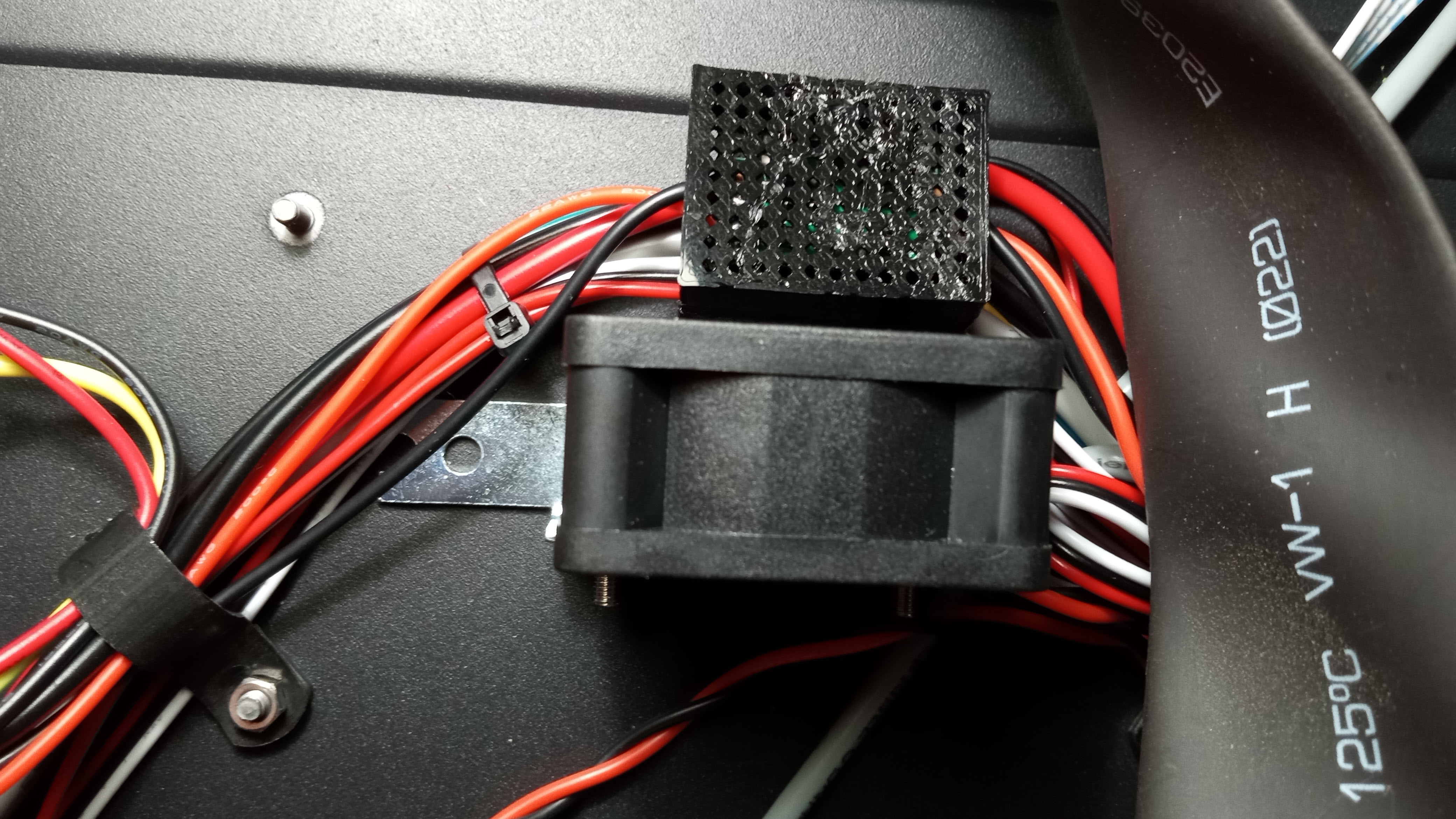
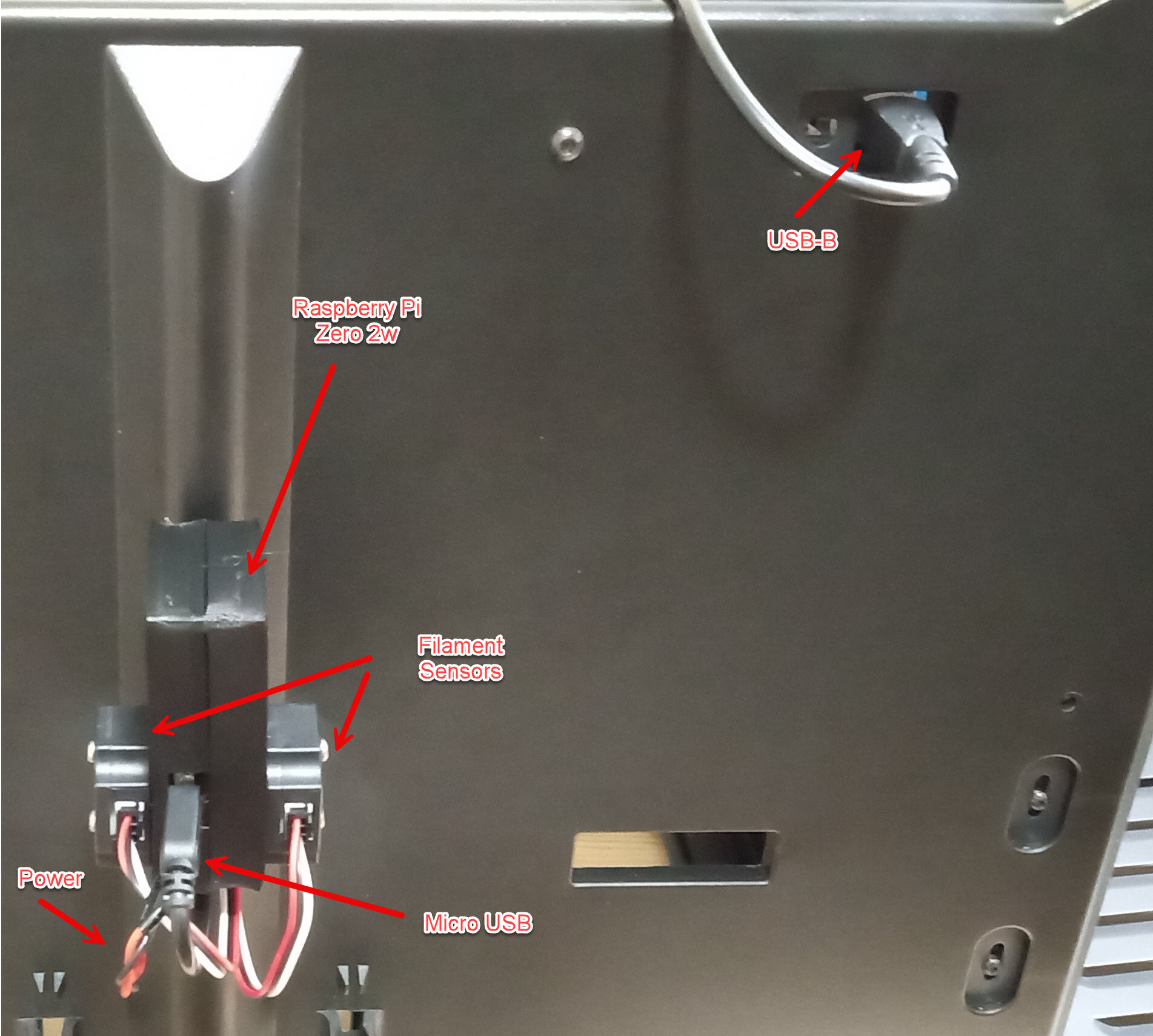
I'll let you decide how you want to protect things from there, but I would recommend a case for the buck converter that allows airflow while preventing it from shorting out, and a case for the Raspberry Pi. I made a case for the converters that you can find the STL for here, which seemed to work alright. I made one for the Pi Zero 2w as well, which worked with some glueing, but I wouldn't necessarily recommend it for someone else in hindsight. If you want to try it or modify it, the STL is here. The idea was to make a complete mounting solution for the filament sensors and raspberry pi, and it works, but I didn't think about the fact I was gluing the pi shut into the case with my approach, which ideally I would have liked the pi to be more easy to access. Below is what the Raspberry Pi wiring, cases, and the buck converter case look like in my setup. The creator pro's back panel has a convenient slot that you can slip the USB B cable for the Pi to talk to the MightyBoard, which you can route inside of the case and through the cable loom and out to the raspberry pi.
With these steps complete, make sure you've got good insulated connections, and go ahead and try to power your printer on. If everything is good you should start seeing lights on the pi flash showing it is getting power, and it should eventually show up on your network.
Configuring Mainsail and Klipper
At this point, you have a Raspberry PI hooked up to your printer, with MainsailOS installed on it. There are a few things left to do in order to get your printer talking to the Raspberry Pi.
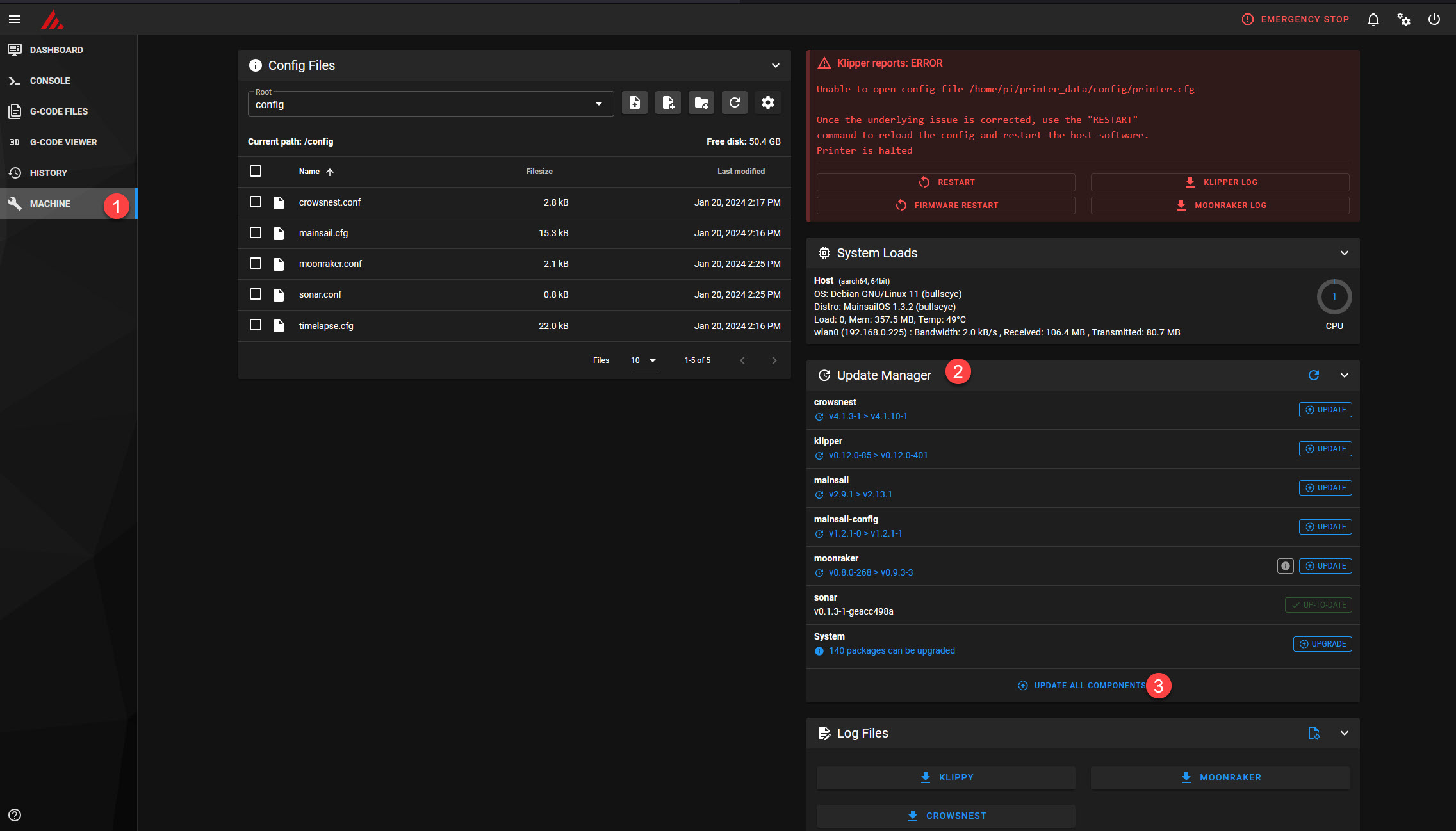
Run Updates in your update manager
Your first step is to access the updates manager in mainsail, and update all of the components. This should be reachable on the Machine tab, which is http://mainsailos.local/config/
Adding your first printer.cfg file
Klipper uses a printer.cfg file as the primary file for understanding how your printer is setup--if you make changes to the wiring or setup of your printer the printer.cfg is what you will need to update (Klipper allows you to include other configuration files into your printer.cfg, so you could organize your configuration between multiple files ). When you're just getting started, its best to have a basic configuration with just the things you need, and then you can expand it later as you modify your printer or want to tune things better. I've created sample printer config files with the most basic creator pro configuration, that should work for a factory creator pro, and the final file that is configured from going through future steps in this process, which can be retrieved from this github repository. I make no guarantees on this configuration, other than that it works with my factory Creator Pro--it isn't impossible there is differences from printer to printer, so once you have a config you'll want to test and tune things later. For anyone following along with a different type of printer, see the Klipper Config Examples repository, odds are there's a config out there matching your printer model as well. To use this file you will save the file on your computer, and then in the config files part of your machine configuration in Mainsail you can upload the printer.cfg file. Once uploaded, you'll want to perform a restart of Mainsail to refresh this configuration. There are other config files that come with Mainsail, you can look more at these if you'd like, I won't go into more detail on this here.
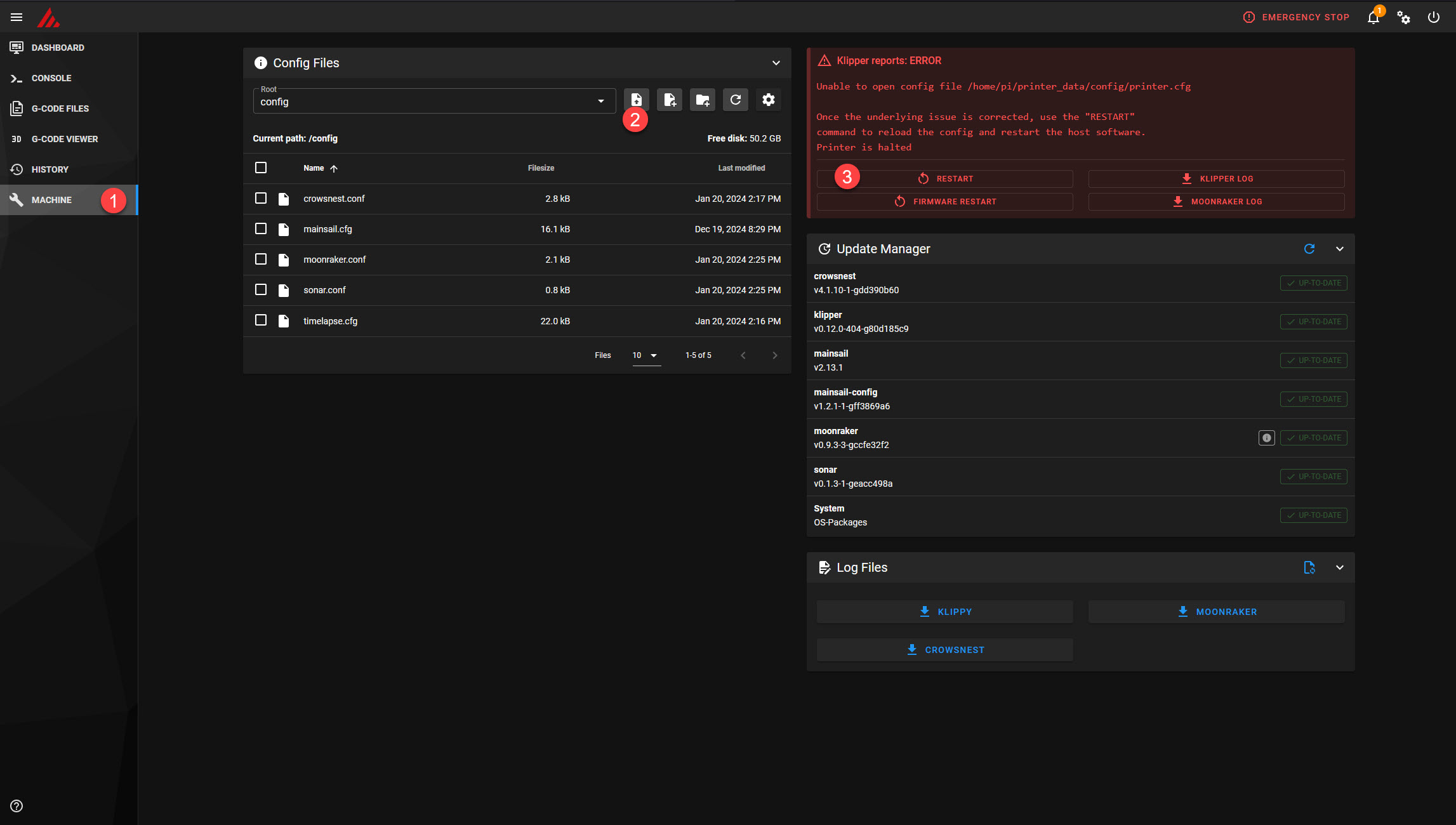
After you've added the printer.cfg file and restarted, it will be utilized in the next step in order to flash the firmware on the printer's control board.
Flashing Klipper onto your MightyBoard
When you imaged mainsail onto your SD card, you should have configured settings for SSH, either through setting a username and password to connect with, or by setting up key based authentication. You'll need to use an SSH client to connect to your printer. PuTTY is a commonly used client for this purpose on Windows, and on Linux or MacOs you should just be able to connect via the terminal. Look elsewhere for instructions for configuring SSH and connecting remotely to your Raspberry Pi (alternatively, you can wire up a mouse, keyboard, and monitor to perform these steps as well).
You can find the official instructions for flashing Klipper, but I'll walk through them as well, and provide some information specific to the Creator Pro. The first step is going to be compiling the code for the controller, which is done with the following commands:
cd ~/klipper
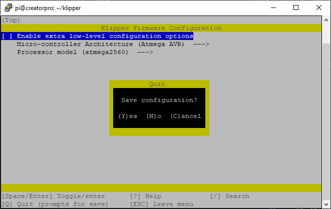
make menuconfig
You will be presented with a configuration interface, make sure that you have "Atmega AVR" set for the Micro-controller Architecture and "atmega2560" set for the Processor model. These settings will ensure that the code is correctly compiled for the MightyBoard. Once these values are set, you can press Q to leave the menuconfig, and Y to save the config.
Next run
make
Which will run through the compilation of the firmware binaries and make it so they are ready to be sent to your MightyBoard. Next you will need to identify the name of the serial port that your MightyBoard is connected to the Raspberry Pi with, you can do this by running
ls /dev/serial/by-id/*
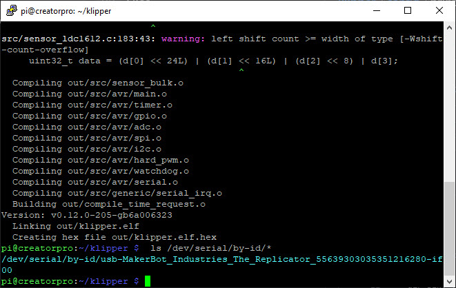
This name will be unique to your printer, so you'll have to ensure you are using the correct name output for your printer in the next steps. Next you will actually flash the MightyBoard with an avrdude command, which will remove the existing SailFish firmware and replace it with the Klipper firmware. This is a destructive step, and I don't have instructions for returning to SailFish, so make sure you're OK with the path ahead before performing this step. Run the following command, replacing the part in <brackets> with the port that was output above instead.
avrdude -v -c stk500v2 -p atmega2560 -P <Add your serial port path like /dev/serial/by-id/full-serial-port-name> -b 57600 -D -U out/klipper.elf.hex
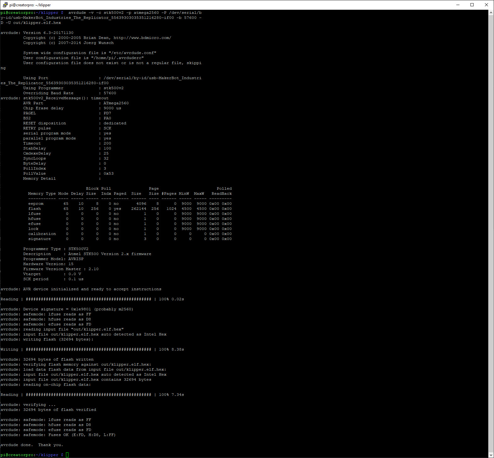
This command is using avrdude to send the klipper.elf.hex binary to your MightyBoard, using a baud rate of 57600. For me this was one of the most finicky parts of getting the firmware setup, as it was difficult to get this command to complete successfully--my first few times running it I kept seeing timeouts receiving messages from the board. Your best chance here is to restart the printer and retry running this command if you run into these timeouts, it should succeed eventually and once it does you won't have to run it again. After running this command, go to Mainsail and perform a restart. Assuming everything worked correctly, the errors in Mainsail should be gone now, and you should now have a functional printer. Keep in mind, that you're printers characterization is almost certainly different from mine. You will have to spend time dialing everything in and tuning all the different pieces. For next steps, I recommend running through the Kilpper Configuration Checks to verify everything is functioning and responding correctly, as well as tuning the PID for the extruders and bed.
Future steps I'd recommend are tuning the Rotation Distance for your motors, and going through the Bed Leveling configuration (if you are going to be using something other than the BL Touch, or want to print without the BL Touch first). After you've tuned most of your settings you should be ready for a test print then, where you can start to identify issues and adjust based on the quality of the print. I recommend starting with a Calibration Cube and Temperature Tower, so you can begin to assess the quality of your prints.
Installing a BL Touch
Prerequisites
- $38 - A BL Touch auto bed leveling sensor, with the 2 meter extension cable (other auto leveling sensors or the knock off BL touch models may work alright as well EDIT: I've since tested a 3D Touch sensor with this same process on a different printer, if you're looking to save a little money I can confirm the 3D touch level sensors work identically). The 1M extension is slightly too short, but you can splice and extend it with the included smaller cable as well, or make your own cable.
- $2 - 2x 50mm long M3 machine screws -- I used Philips head because that's what I had, but you can do Allen head to keep them consistent with existing screws.
- $1 - 2x 10mm long M3 machine screws for mounting the BL touch
- An Allen key set with a 2.5mm or 3/32" Allen key.
- (Optional) 4 pin DuPont connectors, or a soldering iron to help with cleanly connecting to the printer.
What is a BL Touch
A BL touch is a bed leveling sensor that enables a printer to support automatic bed leveling. The BL touch sensor utilizes a hall effect sensor and a magnetically actuated probe. The actuator lowers the probe below the print nozzle to allow it to take measurements at different locations on the print bed, allowing it to create a mesh of the shape of the bed. The mesh that the BL touch creates then allows the part being printed to be warped to the form of the bed so that the nozzle can move up and down according to the actually shape of the bed. The probe is then raised automatically after measurements have been made, and the nozzle will be able to print without being interfered with. The probe also doubles as a replacement for the normal Z endstop on the printer, as when the probe lowers and retracts from the bed it will be used to find the Z axis zero height. Similar approaches can be done with micro switches, a CL Touch, or many other options, but the ultimate goal is making it so that you don't have to level your bed ever again (or at least exceedingly rarely), and have near perfect first layer prints.
Installation Process
The process for installation is going to require getting your hands a little dirty and taking apart the printer to get at the main board. The main board is located on the bottom of the printer under the finned cooling grate. If you haven't already, follow the instructions above for getting at the control system for the printer. It will be easier to route the cable if you take off both the front and back panels, as you can fit the sensor and other cables in the existing cable loom to keep the cable routing clean.
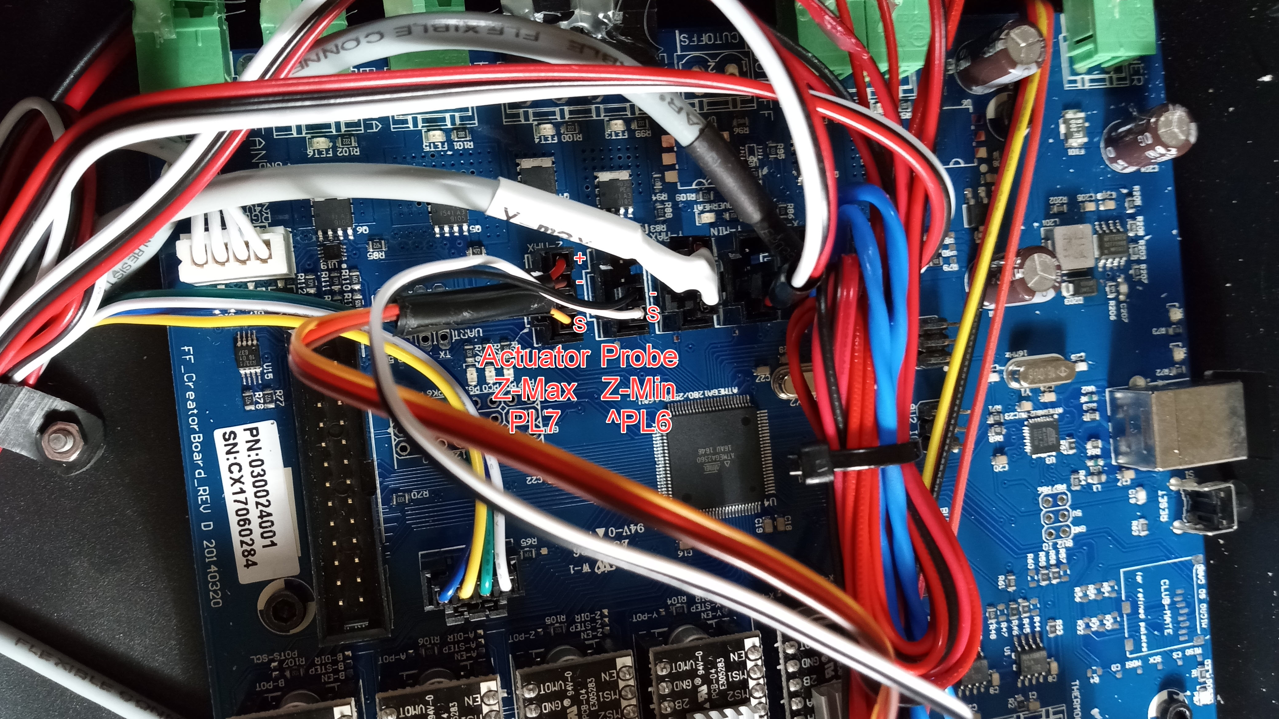
The BL Touch has two separate cables, one of them is for the probe's hall effect sensor (white and black), and one of them is to control the actuator (brown, red, and yellow). The easiest way to wire these into the creator pro is to piggyback on the existing Z-Max and Z-Min input pins. First you can remove the existing Z-axis microswitch and unplug it from the MightyBoard. The Z-Min input comes empty already, so nothing needs to be unplugged there. The microswitches on the Creator Pro are 4 pin, and it happens that the pins don't match up nicely with the existing connector on the bl touch actuator cable. You'll want to cut this cable very close to the existing connector, strip the cable about 1/8" at the end, and then crimp on new connectors to it. If you have a 4 pin DuPont connector (the same style of connector that comes with the BL Touch), you can put the crimped ends into that, but otherwise you can just wrap the crimped ends in a little electrical tape and plug them in individually. You'll want to make sure that the connectors when plugged in match up with the below wiring.
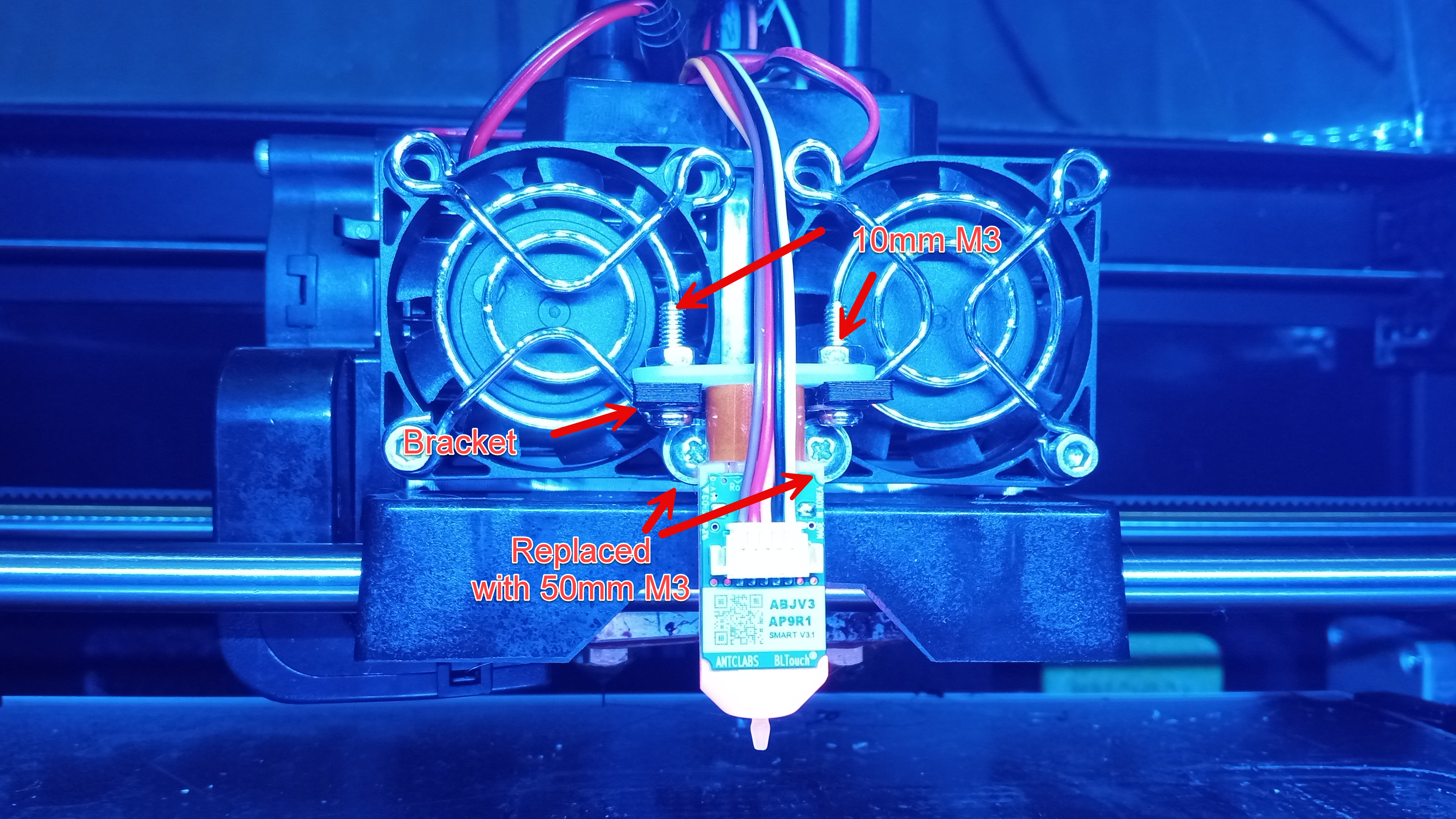
You will run these cables up through the wiring loom, and have them come out on the top of the extruder carriage. I've designed a bracket that you can print out to mount the BL Touch itself upon the extruder carriage. You install it by removing the center two machine screws pictured below, and replacing them with two slightly longer 50mm M3 bolts, and placing the bracket over top of the fan covers. When you take out these M3 bolts its going to be a bit of a pain to get everything back on, because there's spacers and heat sinks that are bolted that will fall out easily, so try to make sure you don't lose the spacers, and when you put them back in try to put them in all together. After the bracket is installed, you'll bolt the BL touch to it with some 10mm M3 bolts and nuts so that it is secured. Once installed you can plug in the cable.
Configuring the BL Touch
There are a few configuration settings that you'll need to change in your printer.cfg file in order to get the BL Touch operational:
[bltouch]

sensor_pin: ^PL6

control_pin: PL7

x_offset: -16

y_offset: -44

z_offset: 3.250


[safe_z_home]

home_xy_position:  101.5,113

speed: 50

z_hop: 10

z_hop_speed: 5
Ideally these settings should work for you if you correctly followed the wiring. Depending on your print and setup for the bracket, its possible it will be slightly different, so it is best to follow the Klipper Probe Calibration procedure. This will allow you to accurately measure your x, y, and z offsets. The x and y offsets are mostly utilized for the bed mesh calculations, but the z offset is crucial as it tells the printer how far your probe and nozzle are from each, which means that is effectively the measurement that gets used to determine how you're first layer gets printed.
Installing Filament Runout sensors
Prerequisites
- $14 - 2x Filament Runout Sensors - One for each nozzle, I used ones from Creativity that were $7 a piece, but I'm sure others will work, or you could potentially make your own if you have some microswitches lying around. Creativity 3D Printer Filament Runout Sensors.
- (Optional) 4 pin DuPont connectors, or a soldering iron to help with cleanly connecting to the printer.
What is a filament runout sensor?
The filament runout sensors are nice to have. They will make it so if you're printer runs out of filament the print will be paused midway allowing you to swap in new filament and continue to finish the print up. One key caveat with this is that you need to ensure that your spools will empty freely without the filament holding on to the spool, because the sensors work by a microswitch that deactivates when filament no longer is present inside the sensor. Some spools will bend the end of the filament into the inside of the spool, which may get stuck, so you'll need to check spools to make sure the filament will fully release. The sensors are simply microswitches with an indicator light.
Installation Process
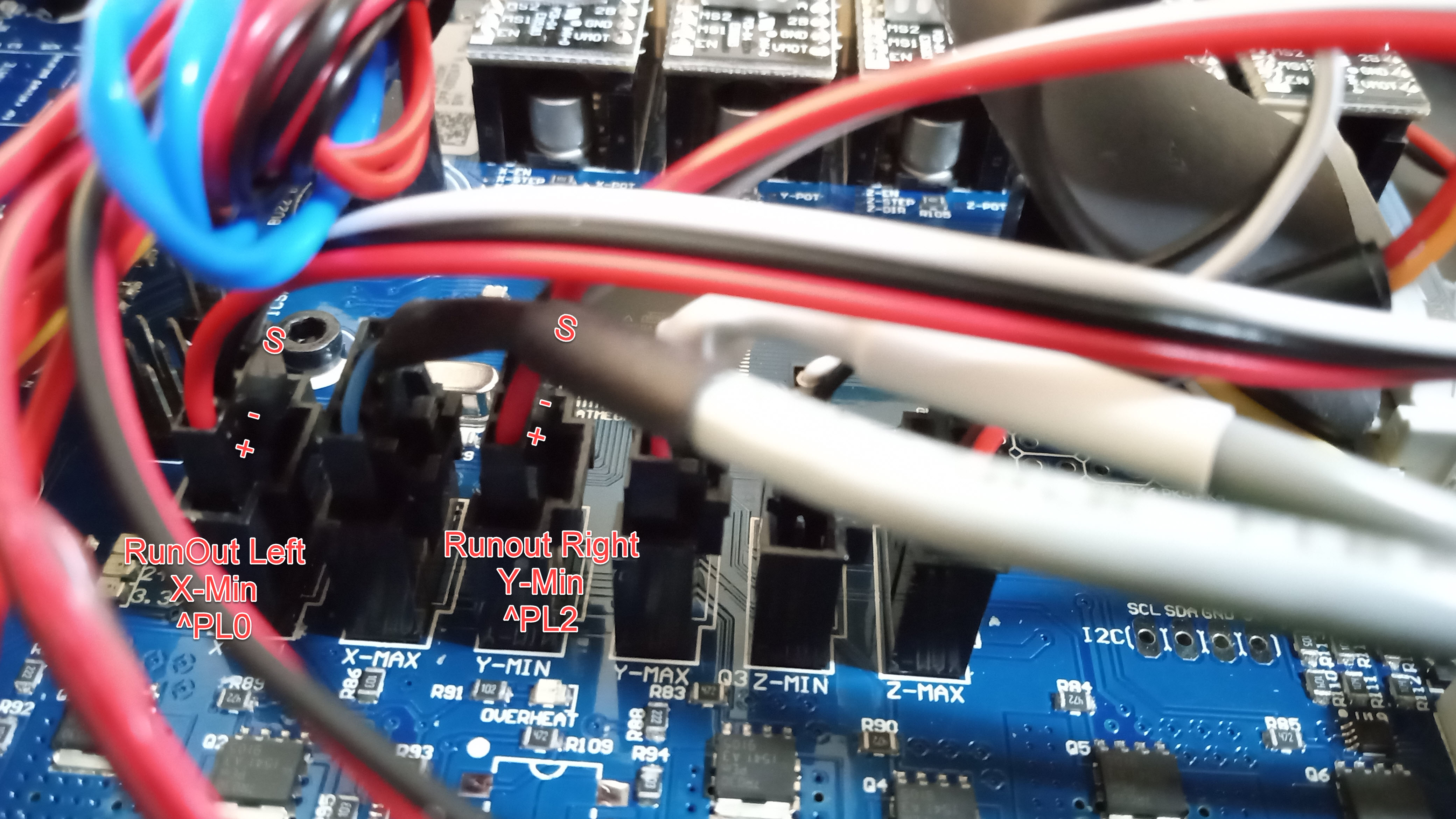
The wiring to the MightyBoard is fairly straightforward, you'll want to wire them into the empty X-Min and Y-Min slots on the board, as the Creator Pro doesn't come with a X-Min or Y-Min limit switch. Once again, the connectors that come with the sensors aren't going to work, so you'll need to make new ones, or solder the wires directly in. The wiring for them should look similar to below.
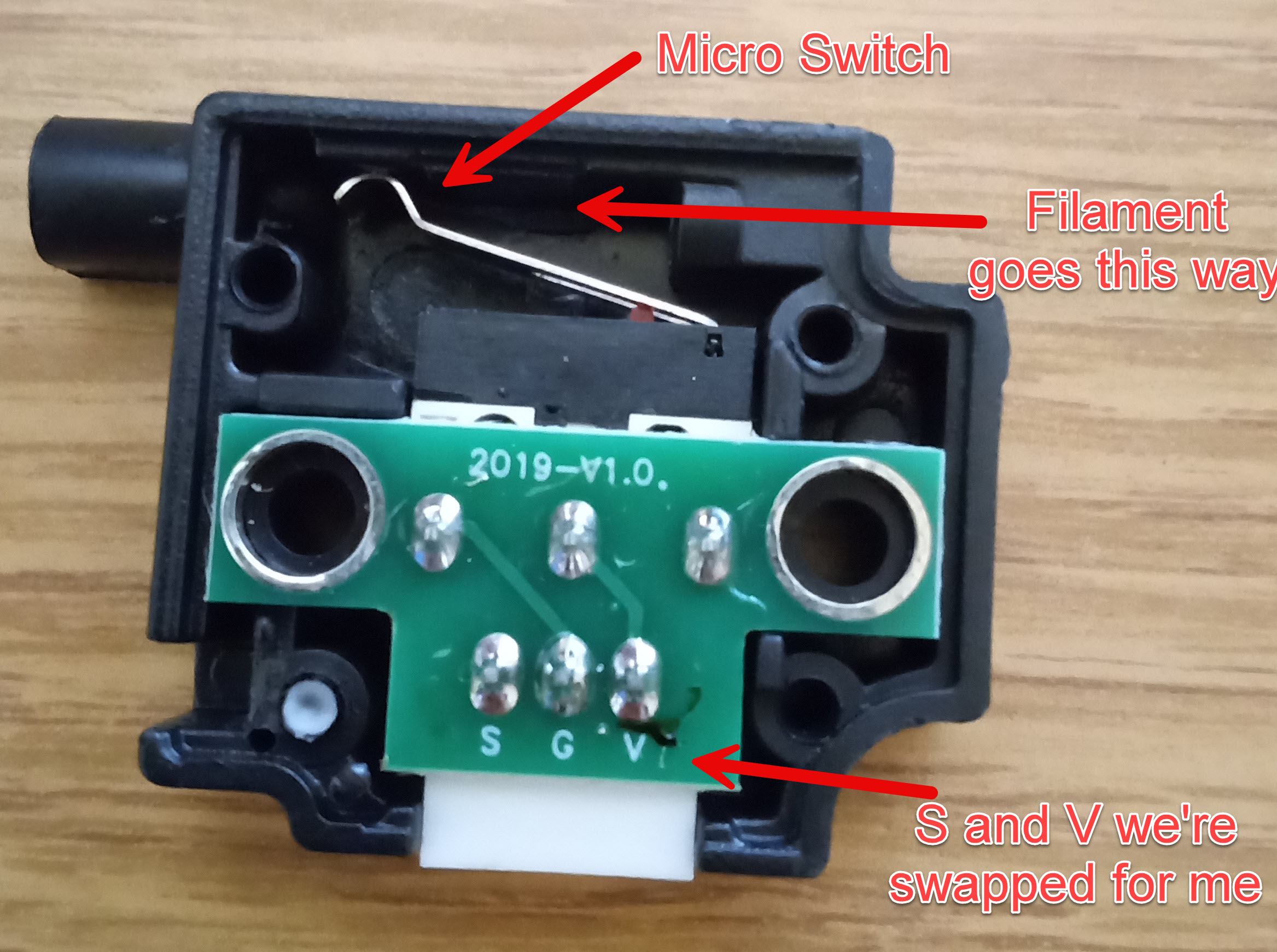
You can similarly route the cables part way through the cable loom, and then have them come out on the back of the printer near the filament spools. One caveat that I ran into with my sensors was that the cable that came with them was actually very counterintuitively wired with the white cable going to power rather than signal, so you'll want to be a little careful with how you wire these up. Below is what the inside of one of these switches look like, and that's what I used to find out (after far too long) that my sensors were wired incorrectly due to the cable from the manufacturer. I was able to pull out the ends from the connector and rearrange them fairly easily so that white would go to S and red to V.
Once you have those wired up, you can glue or otherwise mount them in place so that filament can pass through them. The photo earlier displaying the Raspberry Pi shows my setup with the filament sensors, which I have attached to my raspberry pi case.
Configuring the sensors
Once the sensors are wired up, you'll want to configure them in printer.cfg to make them operational by adding the following:
[filament_switch_sensor left]
pause_on_runout: True
event_delay: 10.0
switch_pin: ^PL0
runout_gcode:
  M117 Filament out

[filament_switch_sensor right]
pause_on_runout: True
event_delay: 10.0
switch_pin: ^PL2
runout_gcode:
  M117 Filament out
This configuration sets both of the sensors up. Depending on the wiring, and your preferred perspective, you may end up swapping the names for left and right. This configuration is also specifying that if the printer detects filament runout it should pause the print, and the event delay is to try and help prevent erroneous triggering of the sensors. The runout G code will display the test "Filament out" on your printers LCD. Ideally, these should just work for you. To test them, you can run a query to see their current status in MainSail by sending the following command to the printer:
QUERY_FILAMENT_SENSOR SENSOR=left
Try this with filament in the sensor and then again without, it should tell you whether or not it thinks filament is present. For the other sensor, switch the sensor name to be "right" to query the right sensor. If the sensor is responding differently with and without filament present then the sensor is wired correctly, otherwise you might have an issue with your wiring, so trace the wires, or try the Z microswitch that you removed for the BL Touch in the same pinout to see whether you can query a value and make it change with your pins. If, for some reason, the query is responding but the status is flipped (it thinks there's filament when there's not, and vice versa), you can add an ! in front of the switch pin to swap the pins logic.
Installing a Glass Bed
- $24 - a 230mm x 150mm sheet of glass, for example this piece of Borosilicate with polished edges
- $6 - A mechanism for attaching the glass to the build plate, I got these adjustable printer clamps, they were slightly too small so I just bent them open a little more and they worked perfect. Another option is to buy some paper clamps such as these ones, but I find that the metal vibrates too much when printing, and removing the metal every time is a pain, so I prefer the ones with set screws. You can alternatively 3d print a system for attaching the glass to the build plate.
- (optional) A putty knife and some rubbing alcohol
I've had good experiences with glass beds for 3d printers, as they provide a smooth flat surface and heat fairly well. The existing bed on the printer was worn and a mess (pictured below), and I didn't want to even think about printing on it. The process for switching to the glass bed wasn't too bad. You will want to remove the existing blue mat on the printer ideally, I did this with a putty knife and then took it apart to soak in rubbing alcohol to help the remove leftover adhesive. After you've removed the existing plate, you just add the glass bed and affix it to the build plate. For printing adhesion on glass, I personally use hair spray, specifically Aqua Net Extra Super Hold as it is cheap and easy. I normally reapply a bit before each print, and again after a few prints. Once I start noticing adhesion issues, I'll clean it with soap and water and start over again. There are other products out there that can also help, such as Protopasta's Magigoo.
Conclusion
That's it for the modifications that I've made and documented so far for my Creator Pro. If, for some reason, you need more places to setup I/O for your printer beyond the limit switch slots we are hijacking for the Runout Sensors and BL Touch, the Creator Pro does have a set of external pinouts that can also potentially be used for this that are labelled as MEGA 1280 I/O pins. I haven't experimented much with these yet, but I'd expect they'd work just as well. There's also UART and I2C pinouts available as well, which I haven't tried out either. The pinout schematic linked in the references section is an incredible resource if you want to go beyond what I've talked about here, and want to tinker further--that's what I used to figure out quite a bit of the pinouts used.
Hopefully this helps someone else out there on the journey I went on, but I've already gotten utility out of it by going through a similar process with a RepRap printer that I made some similar modifications to. Happy tinkering!
Resources
Creator Pro printer.cfg—Basic configuration for printer with and without BL touch.
Buck Converter Case STL—Case I made for the buck converter.
Raspberry PI Zero 2w STL—Case I made for the raspberry pi zero 2w.
BL Touch Mounting Bracket STL—Mounting bracket I designed for the BL touch to mount it on the creator pro.
Creator Pro Filament Spool holder STL—The spool holder I use for both filament spools on my creator pro.
A reference Creator Pro configuration from pedrsj—This was helpful in getting a working configuration for me.
Klipper Configuration Checks—Recommended checks to run on a printer running Klipper after configured.
A datasheet for the ATMega 2560 and ATMega 1280—This is the microcontroller at the heart of the mighty board, and can be useful for trying to figure out pinouts.
A Schematic for the Creator Pro MightyBoard—This is an essential resource for trying to figure out how to match pins in the firmware to pins on the MightyBoard.
Build It Make it Video on powering Raspberry Pi with your printer—This is a helpful video on figuring out how to power your raspberry pi with your printer's power supply.